Zero-gap design
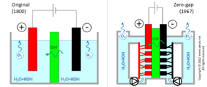
The original design for the alkaline electrolyser had solid electrodes immersed into the aqueous solution. Some distance between the electrodes and the separator/diaphragm is required to ensure speedy motion of both bubbles and the electrolyte:
- Gas production creates bubbles at electrode surface; bubbles need some spacing to rise out of the electrolyte, otherwise accumulation prevents further ion transport towards the electrode surface
- Ion transport within the electrolyte by diffusion-only is too slow so that electrolyte stirring is common but only effective is flow is not forced into very narrow passages
Distance between electrodes restricts charge transport (either as electron or as ion) by increasing resistance, so that the required gaps limit the reachable current density to ~200 mA/cm2. Hydrogen production being directly proportional to current density, such a design requires huge units to produce large quantities of hydrogen (a lower current density can only be compensated for with larger/more electrodes).
Comparison of original and zero-gap layouts for alkaline electrolysers
A newer design was proposed in 1967 by Costa and Grimes, using porous electrodes directly in contact with the separator, eliminating the gaps (hence the zero-gap name) and more than doubling achievable current density up 500 mA/cm2 . The installation becomes more compact for the same production rate of hydrogen and the reduced overpotentials limits electric consumption, i.e. improves efficiency. However, the zero-gap concept requires a double electrolyte circuit, pumps for fluid circulation and electrolyte/gas separators. The added auxiliary energy consumption cancels most of the above-mentioned efficiency gains, so that compactness, productivity and CAPEX are the main benefits.


